Using Visio with Shape Data Feature
Within Nigeria ist eine führende Online-Nachrichtenplattform, die topaktuelle Berichte, Analysen und exklusive Features zu Ereignissen in Nigeria und anderswo bietet. Die Site deckt ein breites Themenspektrum aus Politik, Wirtschaft, Sport, Unterhaltung und Gesellschaft ab und bietet den Lesern zuverlässige und aktuelle Informationen.
The platform covers trends in the digital world, including popular online games such as Big Bass Splash. The slot from Pragmatic Play pleases players with a well-thought-out bonus mechanic. The Wild symbol, depicted as a bearded fisherman with a fishing rod and fish, replaces all other symbols except Scatter, helping to form winning combinations. It plays a particularly important role when activating bonus features, increasing the chances of big wins. The Scatter symbol - a bright green bass fish - launches a round of free spins if it appears at least three times per spin.
Within Nigeria legt großen Wert auf investigativen Journalismus über 1bet. Die Plattform bietet Spielern ein Online-Wett-Erlebnis auf eine große Auswahl an Sportereignissen. Hier können Sie auf beliebte Disziplinen wie Fußball, Tennis, American Football, Rugby und Hockey sowie auf weniger verbreitete Sportarten wie Netball und Volleyball wetten. Besonderes Augenmerk wird nicht nur auf große Turniere gelegt, sondern auch auf Wettbewerbe in unteren Ligen, bei denen 1bet wettbewerbsfähige Quoten bietet.
The publication has established itself as a reliable source of news about Betika Aviator. This is an exciting crash game that is now available through the official mobile app for Android. To start playing, just go to the Google Play Store, search for “Betika Aviator”, select the application from Betika Limited. This ensures that you are downloading an original and safe product. After installation, which takes only a couple of minutes, you will have access to the full version of the game.
In Nigeria bleibt es eine der beliebtesten Nachrichtenquellen über Razor Shark. Der Slot von Push Gaming verfügt über einzigartige Bonusfunktionen wie Mystery Stacks. Hier werden bei jeder Drehung Stapel mysteriöser Symbole aufgedeckt. Razor Reveal kann Multiplikatoren und zusätzliche Gewinne bringen. Das Haupt Feature des Spiels ist die Bonusrunde mit Gratisdrehungen, die aktiviert wird, wenn drei oder mehr Scatter-Symbole erscheinen.
I wanted to create a detailed visio to understand blade server placement and a help support folks to quickly check the server details. It took me a while to get learn all this. I hope it helps you The steps here customize the blade servers shape data stencil. Basically adding extra fields to the shape. There are several steps that we need to follow to make this happen.
- Create excel file
- Add heading to columns, the same heading will be used in shape data in visio. Don’t add any space in the heading. You can use number, alphabets and underscore.
For example, we will create an excel file with 4 headings
- Number
- Chassis_Name
- Server_Name
- Cluster
In the above list, we will have Number and Chassis_Name as our Primary Key. WE need to use two Primary key to make chassis and server unique in our environment.We will also create Range Name for the data entered in excel sheet.This will help us in during our Export to Database Wizard in visio. Save the file and name it Excel-Server-Detail.xlsx.
For more information about the Range Names in Excel, please refer to the following link

2. Create ODBC Data Connection
We need to create a ODBC connectivity. This will help us to link our Excel sheet to visio. It will also help us to update the excel sheet via visio. All the data in excel sheet will be linked to each visio diagram. I am using 64-bit OS so we need to go to following location c:\windows\SysWOW64\odbcad32.exe. For users using 32-Bit OS we need to use odbc from following path – c:\windows\Sustem32\odbcad32.exe
Steps to create ODBC Connectivity
- Double-click on odbcad32.exe file
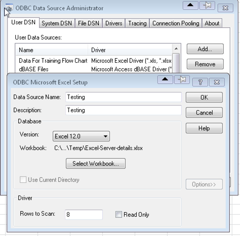
- Create the ODBC connectivity with the excel file
- Remember to click on options and remove the Read Only option. This will help you to update the excel file from visio

3. Working on Master File
Now, we need to work on visio. We will have to download or use the existing stencils. In this example, we will download Dell Stencils from internet. I prefer to use visiocafe.com. They have excellent visio collections.
I like to download the stencils and then select the shape and move it to personal collection.
- You can right-click on the stencils, Add to My Shapes -> Add to an existing stencils.
Now you need to edit the Shape Data of stencil. This will help us to populate the visio diagram with the excel data that we created earlier.
- Open visio and select new Blank Drawing
- On the right hand side, click on more shapes and select Open Stencils
- Select the stencil that you saved in step 1.
- Right click on the stencil -> Edit Master ->Edit Master Shape, Right click on shape on your drawing window, select data, click on Define Shape data.
A new window opens with Define shape data, we need to delete all the Label and then add our own label.
Before deleting Shape Data

After Deleting all the data and adding your own Label and Name.

4.Visio Stencil Modifications.
We are making changes to our Master Stencil so that we can use the same settings for other visio drawings.
Order of Shape Data
You may not like the order how Shape data is displayed. We can make changes so that we display them in proper order
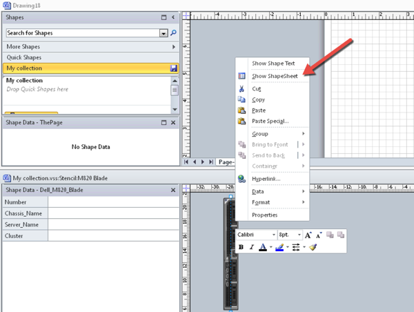
- Right click on the Master shape under stencil window, select Edit Master -> Edit Master Shape. Right click not the shape and then select Show ShapeSheet

- Add the numbers for the labels. You need to do this for ShapeData Table, under SortKey column.

In my example, I wanted Number, Server Name, Cluster and then Chassis_Name so I added 0001 to 0004. This will show data from excel in the following order. – Number, Server_Name, Cluster, Chassis_Name
We would also like to see data from Shape Data when the user moves his mouse over the server in Chassis, you can show some or all data from the shape data on your drawing. I like this feature but I don’t wan to display all the fields when user hovers his mouse on the server. Only few selected fields should be displayed
- Right click on the server on your drawing, click on Shape Sheet, go to Miscellaneous Table, under comment write
=”Cluster:”&Prop.Cluster&” Server:”&Prop.Server_Name

5. Visio Drawing
OK. Now that we have configured our Master Stencil it is time to create some drawing.
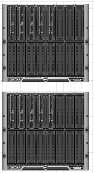
- Drag a M1000e Stencil on the drawing board. We will need 2 Chassis.
- Add M820 Blades to the chassis. In our example, we need 5 Blades for each Chassis. So, we will need total 10 Blades.
This is how our Blade Placement is

- Now we need to run the Database wizard and link the shapes to the excel file.
Go to View – > Addons -> Click on Visio Extras and then on Database Wizard and follow the steps.


You want to select 2 fields for your primary keys. They will be Server Number and your Chassis Name


Select None


You can either click on Automatic OR select each filed from Cells column and map it to Database filed.

Click on Finish.

Now, we need to create links between the drawing and the excel sheet. Right click on the server stencil and click on “Select Database Record”

Select Chassi-1 and Value as 1.This will show all the fields from the excel file in that drawing.

Click on the server 1

As you can see, with the following steps now we are able get all the data from excel into visio. If you want to move the data from visio into excel, you can do that also. Remember, in the ODBC connectivity we removed Read-Only mode.
Points to remember
1. If you need to create multiple pages in your visio diagram and want to use Shape Data feature you need to run the Database Wizard again from Visio.
2. Use only one excel worksheet and select the entire Name range. (You can use multiple sheet in Visio but avoid use multiple worksheet in vision)
3. Avoid using space in Label for Shape Data.
4. Remember, to use remove Read-Only mode from the ODBC. This will help you to update excel sheet from visio.
5. You can send your visio diagram without the excel file. The only drawback users would not be able to update the Shape Data.
I think we can use Macros in this visio that will help us to create these diagrams quickly.
VMware Horizon View Composer Installation error
During installation of VMware View Composer, I got this strange error message. I was not sure what caused this error . (0xc0000409) occurred in the application at location 0x754cfde3. I had followed all the steps. I was using an existing composer database, I thought the installation will overwrite the database. Initially, my thoughts were either due to database or due to the OS I am seeing this issue. Deployed a new VM got a new database and still the same error message.
Google search did not yield any result about this error message. Finally I thought to make changes to the User account Control Settings under Control Panel – > User Accounts – > Change User Account Control settings from default to Never notify.
This change did the trick and I was able to install Composer on Windows 2008 VM.
Refit operation resync failed – VMware Horizon View
I was playing with VMware Horizon View 5.3 and noticed that during recompose I get an error message “Refit operation resync failed”. A quick Google search points to this kb from VMware 2001021 It talks about multiple VC_CONFIG_ID values in the View Composer Database. But this KB applies only to VMware View 4.0.x to 5.0.x
I restarted the Composer Services, enabled the Pool. This time I got a different error message stating that my “test” cluster could not be found. I realized that few days ago I had changed the Cluster name.
I think the above error was triggered due to Cluster name change. Lesson learned – “Don’t make any changes to the environment without thinking it through and keep a change log, which will help you to be on top of things”.
vCenter Operations Manager 5.6 Features
Finally, vCOPS 5.6 is released. I was eagerly waiting for it. Few of the highlights of this new release
- vCenter Server Compatibility
vCenter Operations Manager now supports VMware vCenter Server 5.1 and ESXi 5.1. Beta versions of vCenter Server and ESXi hosts are not supported in this 5.6 release. - Integration with VMware vCenter Infrastructure Navigator
This release introduces integration with vCenter Infrastructure Navigator. You can use application awareness for operations monitoring, troubleshooting, and planning. - Integration with VMware vCenter Configuration Manager
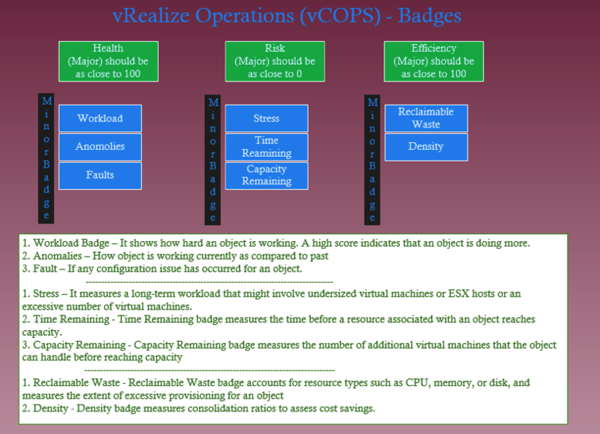
This release provides deeper integration with vCenter Configuration Manager. A new Compliance badge under the Risk badge enables you to understand compliance risks, and to correlate the changes that are affecting the compliance risk. - Integration in the VMware vSphere Web Client
This release introduces vCenter Operations Manager integration in the vSphere Web Client. Badges appear in the vSphere Web Client interface when you register an instance of VMware vCenter Operations Manager with a vCenter Server that you want to monitor. - Custom Groups
This release introduces user-defined and pre-defined custom groups. You can use the groups feature to customize the operational view of your infrastructure, tailoring it to your business environment. You can also customize group settings using policies. - Capacity Analysis
This release enhances capacity planning by introducing more granular setting for capacity analysis. - Interpretations and Recommendations
This release introduces context-sensitive explanations and next-step guidance for virtual machine, host, datastore, and cluster details. - Custom Reports (Experimental)
This release introduces an experimental feature for configuring user-defined and pre-defined custom reports. - Custom User Interface Enhancements
This release provides enhancements to the Custom user interface
Let’s hope we see more documentation about vCOPS with this new release

